
Use the following steps to tune up your LeakTrac for a busy season or to address performance issues. If you’re stumped or would rather have us do a complete tune up you can send your unit into Anderson Manufacturing to be serviced. Just call and give us a heads up that it’s coming!
What You’ll Need
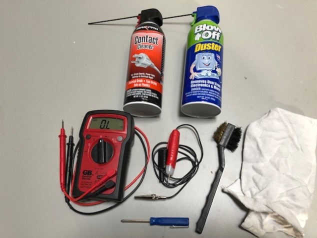
- Electrical Contact Cleaner
- Canned Air Duster
- Volt Meter / Continuity Tester
- Clean Cloth
- Small Phillips Screw Driver
- Small Brush
- Steel Wool
Float and Ground Cables
The best place to start is a visual inspection of all cables for any nicks or breaks. The black float cable and the red ground wire are both single wire, so they are especially susceptible to damage. If there are any problems with these cables, replacements can be bought here.
The metal spring clips on the banana plugs at the end of the cables can get dirt under them after continued use and cause a poor connection. To clean, spray the banana plugs with contact cleaner, then squeeze the plug with a clean cloth and twist back and forth. Repeat this process a couple times then spray them off with the air duster.
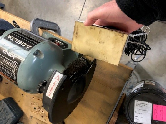
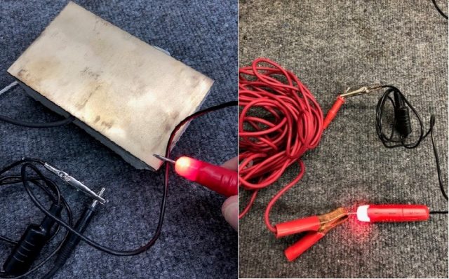
Next, using some steel wool or a wire grinding wheel, clean the brass plate and the red alligator clip. Both of these can get rust or corrosion on them and cleaning can improve the connection.
Finally, using the continuity tester check the cables by placing the tester leads on each end of the cables to make sure you have a good connection on each end.
Probe
Remove the PVC caps from each end of the probe. Using contact cleaner, spray the gold contacts and wipe off any dirt or corrosion with a clean cloth.
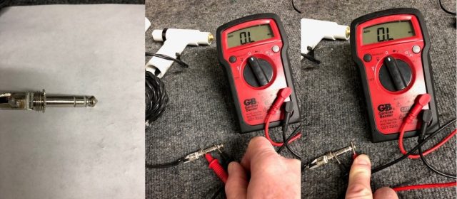
Next check the 1/4” plug and the cables. Using a volt meter on the Ohm’s setting, check the continuity between plug and the gold contacts. Place one of the meter leads on the tip of the plug and the other meter lead on the non-directional end of the probe (the end without the black band). If the wire and connections are good then the meter will give you a reading that there is resistance. If the meter indicates a zero reading then the probe has a broken wire or loose connection and the probe should be replaced.
Repeat the above process to test the other side of the probe. Place the meter lead on the second or middle contact on the plug and the other lead on the directional side of the probe (the one with the black band).
The last step is to check the ¼” plug for any shorts. Using the meter, place the leads on each of the three plug contacts in different combinations: i.e the tip and the middle, the tip and the base and the middle and the base. If you get any type of resistance reading for any of the combinations, you have a short in the plug and you need to replace the probe. There is a chance that the short is caused by moisture in the plug. You can try heating the plug with a hair dryer to dry out the moisture. If you get no resistance reading from the test after drying the plug then the probe is still functional.
Signal Processing Units
LT2100 and LT2200 Models
To check the unit, start by removing the screws and the top like you are changing the batteries. Remove the batteries and check the voltage using the volt meter. The batteries should read 9+ volts DC. If the batteries are lower replace them with new ones.
Next, check the battery holders for any corrosion. Clean the holders with contact cleaner if needed.
Using the contact cleaner, spray the main part of the rotary switch to clean any corrosion on the switch contacts. Turn the switch back and forth 10 to 20 times. Blow off the switch with the canned air. Repeat the process one more time.
Check for other corrosion on the circuit board, especially on the ends of the wide ribbon cable that connects the main circuit board and the front panel. If there is any corrosion, spray with contact cleaner and clean with a brush or cloth.
Tighten any of the cable connectors on the back panel with a wrench.
Reinstall the batteries and the top of the box. Turn the power switch to low, medium and high. You should get a clicking sound an all three positions. If you do not, rotate the switch 10 to 20 times to see if that cleans off any corrosion and improves the clicking.
LT2400 Model
This model has digital circuitry and components and therefore doesn’t require as much maintenance.
Check the 2 AA batteries to make sure they are 1.5+ volts each. Also check the battery clips to make sure they are not rusted or corroded. Turn the unit on to make sure you can switch between all three positions.
Booster Box
Remove the screws and the bottom panel.
Check the batteries, battery holders, and clips. The battery holders and clips should not have any rust or corrosion on the springs or contacts. If they do, you can try to clean the corrosion but it is best to replace the battery holders. These are standard 8 pack AA battery holders. If you cannot find them locally give us a call, we have them in-stock.
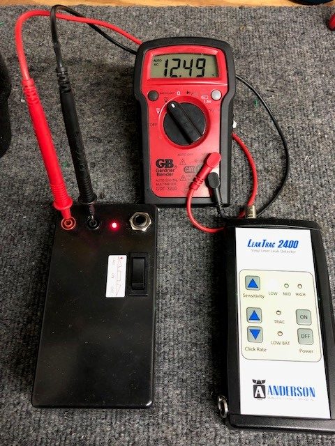
With the batteries reinstalled in the holders, use a volt meter to measure the voltage. Each battery pack should measure 12.5+ volts DC for each pack.
For the LT2100 and LT2200 models, remove the white plastic divider and examine the circuit board for any corrosion. Clean any corrosion with the contact cleaner and a brush or air duster.
Reconnect and replace the battery packs into the booster box.
Next we will check the output voltage of the booster. Turn on the SPU and the booster by using the stitch or button on the top of the booster. (If you have a LT2100 model you will need to plug in the long booster cable before turning the unit on.) Using a volt meter set on AC current, place the meter leads in the two small plugs on the top of the booster. These are the red and black plugs where the float and ground wire connect. You should measure between 10 and 12 volts AC. If you do not get this voltage reading give us a call and our repair technician can help determine the problem.
A video explanation of this process is also available on YouTube. It features a LeakTrac 2100, but much of the process is still applicable for newer versions. Part One covers the Booster Box and SPU and Part Two covers all of the cables and the Probe.
If you run into any issues as you’re performing the tune up don’t hesitate to give us a call! We’re happy to trouble shoot with you over the phone.
